


To establish our Globe better Tele-Communication & Networking has it own value. Networking makes Connectivity easier. What do you mean by “A Network”. I can say Network is nothing but the collection of nodes. You must heard about the term “He has better Business Network.”. Here Network specifies his Business Contacts. When these nodes are real humans. The same story happens in the digital world. Networking is like a relationship. There are various types of Network Topology using which we can establish a Network.
To communicate across WAN or LAN client service architecture is mandatory. Server need to identify clients for connectivity. To connect 2 or more computers there are several hardware and softwares. During LAN Setup normally we requied various network topologies.
Types of Network Topology in Networking
Do one thing tonight when your are in bed, just above you think about a Network. You can take the initial example of a Spider Network. Look closely into this Network you will get the minimum idea about what a Network is. Many ways are there to establish connectivity between more than one nodes. Looking into the difficulties and demand of networking, networking experts designed 3 types of Network Topology.
- Physical Topology
- Signal Topology
- Logical Topology
Under physical Topology various kinds of typologies are possible. Let’s go one by one with Diagram.
1. BUS Network Topology with Diagram
Using Bus topology we use Single Cable to connect multiple Nodes. Watch the Bus topology network diagram below. Here I have a main line which connects 9 computers. One of the major advantages of Bus topology is in-case of a node get failure others not get affected. Bus topology Creates problem while multiple users sending data in same time. Due to this topology stands over a single cable multi-directional data flow creates problem. For single directional data flow this topology is good enough.
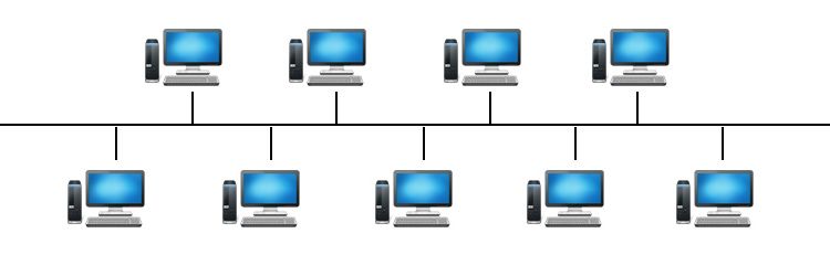
Let’s take an example of Bus topology. Think you are a faculty. What you want is you want to share some books online. Which can be accessed by Students. In such case data flow is single directional. Here Bus topology can meet your demand. Compare to other Topologies Bus topology is Cost effective. It’s not wise to use Bus topology for larger network. Max to max 4 to 5 nodes operates well under this topology. Troubleshooting is very easy in Bus topology. The major drawback of Bus topology is if network traffic is heavy or you have more number of nodes performance decreases during data transmission.
Advantages of BUS Network Topology
1. Cost-Effective: Requires less cabling compared to star or mesh topologies.
2. Simple Installation: Easy to set up and expand by adding new devices.
3. Suitable for Small Networks: Works well in environments with limited devices.
4. Minimal Hardware Requirements: No need for switches or hubs.
Disadvantages of BUS Network Topology
1. Limited Scalability: Performance degrades as more devices are added.
2. Single Point of Failure: If the main cable fails, the entire network goes down.
3. Data Collisions: High network traffic increases the risk of collisions, slowing down communication.
4. Difficult Troubleshooting: Identifying faults can be challenging since all devices share the same bus.
Applications of BUS Network Topology
Early Ethernet Networks: Used in 10BASE2 and 10BASE5 Ethernet standards.
Industrial Control Systems: Found in factory automation and process control.
Small Office/Home Networks: Occasionally used in budget-friendly setups.
2. STAR Network Topology with Diagram
Due to this network looks like a Star it was named as Star Topology. Look at the Star Network diagram below. You can watch a HUB in the Center. Using Star Network we connect various nodes with independent Cable lines. All Cable lines Centrally Connected to a HUB. In this network topology we have to make one node as Server. To establish connectivity under this Network we have to keep Switch On the Server. If Server is off then no nodes will connect each others.
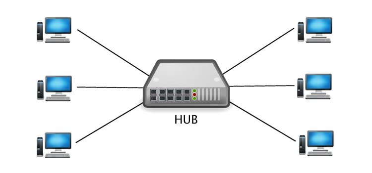
Under Star Topology in-case a node get accidental damage you don’t need to worry about other nodes. As it is one of the popular network topology maintenance of this kinds of networks is very easy and cost effective. If you will notice you can watch this network topology in 90% browsing parlor’s around you. This network topology can establish using with twisted pair, Optical Fibre or Coaxial Cable.
How STAR Topology Works
In a STAR topology, every device has a dedicated point-to-point connection to the central hub. When a device sends data, it transmits the signal to the hub, which then relays it to the intended recipient. The central hub acts as a mediator, managing data traffic and ensuring efficient communication.
For example, in a home network, a Wi-Fi router serves as the central hub, connecting multiple devices like smartphones, laptops, and smart TVs. Similarly, in an office setting, an Ethernet switch may function as the hub, linking computers, printers, and servers.
Advantages of STAR Topology
1. Easy to Install and Manage – Adding or removing devices is simple since each node connects independently to the hub. – Troubleshooting is straightforward because issues are typically isolated to a single connection.
2. High Reliability – If one connection fails, the rest of the network remains unaffected. – Unlike bus topology, where a single break can disrupt the entire network, STAR topology ensures localized failures.
3. Better Performance – Since each device has its own dedicated link to the hub, data collisions are minimized. – The centralized structure allows for efficient traffic management, reducing network congestion.
4. Scalability – Expanding the network is easy—simply connect a new device to the hub without altering existing connections.
5. Enhanced Security – Data transmission between the hub and individual nodes is more secure than in shared-medium topologies.
Disadvantages of STAR Topology
1. Dependency on the Central Hub – If the hub fails, the entire network becomes non-functional. Redundancy measures, such as backup hubs, may be necessary for critical systems.
2. Higher Cost – Requires more cabling than bus or ring topologies, increasing installation expenses. The central hub (switch or router) can be costly, especially for high-performance networks.
3. Limited Coverage – The distance between the hub and nodes is constrained by cable length or wireless signal strength.
Applications of STAR Topology
Home and Office Networks – Routers and switches in LANs commonly use STAR topology.
Telecommunications – Telephone networks often employ a centralized switching system.
Industrial Control Systems – Factories use STAR configurations for reliable machine communication.
Data Centers – High-speed switches connect servers in a STAR layout for efficient data handling.
3. Daisy Chain Topology
While we connect multiple nodes straight forward like a line it’s comes under Daisy Chain topology. The major disadvantages of this types of network is if any node in-between the network breaks the whole network stops functioning. It is easy to maintain and cost effective to Setup. If the end terminals will connect then Daisy Chain topology acts like a Ring Topology.
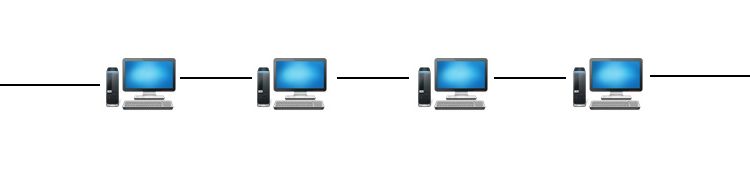
A daisy chain topology is a network configuration where devices are connected in a sequential, linear fashion, forming a chain-like structure. Each device (or node) is linked to the next, creating a continuous pathway for data transmission. This topology is commonly used in computer networks, industrial control systems, and electronic circuits due to its simplicity and cost-effectiveness.
Unlike more complex topologies like star or mesh networks, a daisy chain does not rely on a central hub. Instead, data travels from one device to another in a single direction or bidirectionally, depending on the implementation. While this setup is easy to install and expand, it has inherent limitations, such as potential single points of failure and reduced efficiency in large networks.
How Daisy Chain Topology Works
In a daisy chain network, each device (except the first and last) has exactly two connections—one to the preceding device and one to the next. Data packets move sequentially from the source to the destination, passing through intermediate nodes. There are two primary variations of daisy chain topology:
Linear Daisy Chain – Devices are connected in a straight line, with data flowing in one direction. If one device fails, the entire chain beyond that point may be disrupted.
Ring Daisy Chain – The last device connects back to the first, forming a closed loop. This redundancy can improve reliability, as data can travel in either direction if a break occurs.
Applications of Daisy Chain Topology
Daisy chain networks are widely used in scenarios where simplicity and low cost are prioritized over high-speed performance. Some common applications include:
Computer Peripherals: Devices like printers, scanners, and external hard drives can be connected in a daisy chain using interfaces such as USB or Thunderbolt.
Industrial Automation: Programmable Logic Controllers (PLCs) and sensors in manufacturing plants often use daisy chain configurations for streamlined communication.
LED Lighting Systems: Multiple LED strips can be connected in a daisy chain to simplify wiring and control.
Networking Equipment: Some Ethernet and fiber optic networks employ daisy chain setups for small-scale deployments.
Advantages of Daisy Chain Topology
1. Simplicity and Ease of Setup – Requires minimal cabling and no complex routing, making it ideal for small networks.
2. Cost-Effective – Fewer components and less infrastructure reduce installation and maintenance expenses.
3. Scalability – New devices can be added by extending the chain without major reconfiguration.
4. Low Latency in Short Chains – In small networks, data transmission is fast since packets pass through fewer nodes.
Disadvantages of Daisy Chain Topology
1. Single Point of Failure – If one device or connection fails, the entire network beyond that point may become inaccessible.
2. Performance Degradation – As more devices are added, latency increases due to sequential data transmission.
3. Limited Bandwidth – All devices share the same communication line, leading to potential bottlenecks.
4. Difficult Troubleshooting – Identifying faults in a long chain can be time-consuming.
4. RING Network Topology with Diagram
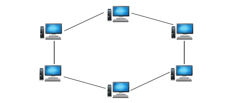
Under Ring Topology we connect nodes in a Circular fashion. Look at the Diagram below. In Ring Topology data transmission is unidirectional. In this topology troubleshooting is difficult. In-case we are expanding or deleting nodes under this network it affects all nodes.
How Ring Topology Works
In a ring network, data packets travel from one device to the next until they reach their intended destination. Each device, or node, acts as a repeater, regenerating and retransmitting the signal to maintain data integrity. There are two primary types of ring topologies:
Unidirectional Ring – Data flows in a single direction (clockwise or counterclockwise). If a device needs to send data to another node, the packet must traverse all intermediate nodes before reaching its destination.
Bidirectional Ring – Data can move in both directions, improving fault tolerance and reducing latency since packets can take the shortest path.
A key feature of ring networks is token passing, a method used to control data transmission. In a token ring network, a special data packet called a “token” circulates around the ring. Only the device holding the token can transmit data, preventing collisions and ensuring orderly communication.
Advantages of Ring Topology
1. Efficient Data Transfer – Since data travels in a predictable path, ring networks can handle high traffic loads efficiently.
2. No Data Collisions – Token passing eliminates packet collisions, making it more reliable than bus topologies.
3. Equal Access for All Nodes – Every device has an equal opportunity to transmit data, preventing bottlenecks.
4. Better Performance Over Long Distances – Signal regeneration at each node reduces degradation, making ring networks suitable for larger setups.
5. Simplified Troubleshooting – The structured loop makes it easier to identify faults compared to mesh or hybrid topologies.
Disadvantages of Ring Topology
1. Single Point of Failure – If one node fails or a cable breaks, the entire network can go down unless redundancy measures (like dual rings) are in place.
2. Complex Modifications – Adding or removing devices requires network disruption, as the ring must be broken and reconfigured.
3. Slower Performance in Large Networks – Since data must pass through multiple nodes, latency can increase in extensive ring networks.
4. Higher Implementation Cost – Requires more cabling and specialized hardware (e.g., token ring switches) compared to star topologies.
Real-World Applications
Ring topologies are used in various scenarios, including:
Fiber Distributed Data Interface (FDDI) – A high-speed backbone network using dual rings for redundancy.
Token Ring Networks – Older LAN implementations that relied on token passing for controlled access.
Metropolitan Area Networks (MANs) – Some city-wide networks use ring structures for reliability.
Industrial Control Systems – Factories and automation systems use ring networks for deterministic data transmission.
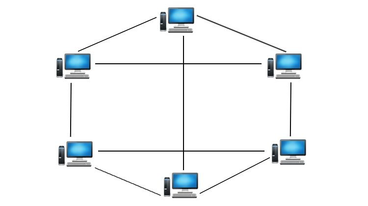
5. MESH Topology
In mesh topology a node stay connected to multiple nodes. The connection we establish in-between nodes is point-to-point type. Mesh topology is two types Full Mesh and Partial Mesh. If each node is having n(n-1)/2 connections that is a Full Mesh. Any single node is less then n(n-1)/2 nodes is called partial mesh topology. Troubleshooting in mesh topology is easier.
Types of Mesh Topology
1. Full Mesh Topology – Every node is directly connected to all other nodes. Offers maximum redundancy and reliability. High implementation cost due to extensive cabling and infrastructure. Commonly used in backbone networks and critical systems like military communications.
2. Partial Mesh Topology – Only selected nodes have multiple connections. Balances cost and redundancy. Ideal for large-scale networks where full mesh is impractical. Used in enterprise networks and internet infrastructure.
Advantages of Mesh Topology
High Reliability: Multiple paths ensure uninterrupted communication even if some links fail.
Scalability: New nodes can be added without disrupting existing connections.
Efficient Data Routing: Dynamic routing protocols optimize traffic flow.
Reduced Latency: Shortest-path algorithms minimize delays.
No Single Point of Failure: Decentralized structure enhances resilience.
Disadvantages of Mesh Topology
High Cost: Requires extensive cabling and hardware.
Complex Setup and Maintenance: Managing multiple connections can be challenging.
Power Consumption: Nodes must remain active to relay data, increasing energy usage.
Overhead: Redundant paths may lead to unnecessary data traffic.
Real-World Applications
1. Wireless Mesh Networks (WMNs) – Used in smart cities for public Wi-Fi, surveillance, and traffic management. Enables seamless connectivity in large areas like campuses and stadiums.
2. Internet of Things (IoT) – Smart home devices (e.g., lighting, security systems) use mesh networks for stable communication. Industrial IoT (IIoT) relies on mesh topology for sensor networks in factories.
3. Telecommunications – Mobile ad-hoc networks (MANETs) support emergency communication in disaster zones. 5G networks incorporate mesh principles for better coverage and speed.
4. Military and Defense – Secure, self-healing mesh networks ensure uninterrupted communication in battlefield scenarios.
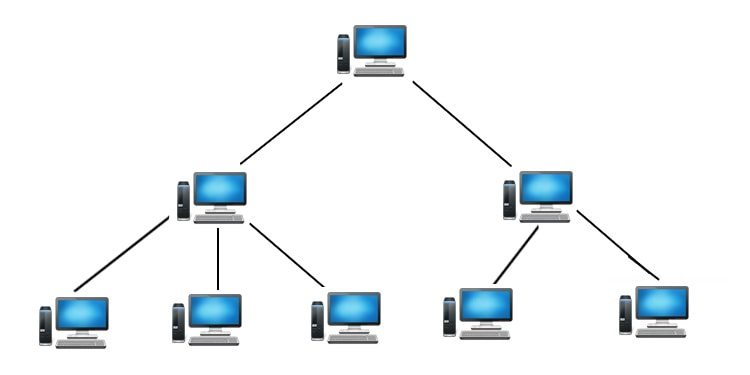
6. TREE Topology with Diagram
I can say the most Complex Network type is Tree Topology. Off Course it has many Advantages but looking into the structure you can easily guess the Complexity. This topology divides the network to multiple layers. The network generally we use under LAN (Local Area Network). The middle layer of this network is called distribution layer. The highest layer is called core layer. In this topology Connection bet-ween nodes are point-to-point. Expanding a Tree Topology is easier compare to other Topologies. Troubleshooting or error detection in tree topology is not so difficult. As there are several layers you can cross check easily. The major draw back of this network is it required more Cables.
Advantages of TREE Topology
1. Scalability – New branches and nodes can be added without disrupting the entire network.
2. Efficient Data Management – Hierarchical organization simplifies troubleshooting and maintenance.
3. Isolation of Failures – A fault in one branch does not affect others, ensuring partial operability.
4. High Performance – Optimized for large networks with segmented traffic flow.
Disadvantages of TREE Topology
1. Dependency on Root Node – Failure of the root node paralyzes the entire network.
2. Complexity – Requires careful planning and cabling, increasing setup costs.
3. Maintenance Challenges – As the network grows, managing hierarchical layers becomes cumbersome.
Applications of TREE Topology
Telecommunication Networks – Used in broadband distribution (e.g., cable TV networks).
Corporate Networks – Large organizations deploy TREE structures for departmental segregation.
Internet Infrastructure – Internet Service Providers (ISPs) use hierarchical routing.
7. HYBRID Network Topology with Diagram
The best example of Hybrid Topology is INTERNET. According to the definition when multiples types of network Topologies comes together it is called HYBRID Topology. In the below network Diagram I used two types of network Topologies Bus Topology and Tree Topology. Keep remember all types of network Topologies are capable to connect each others. As per your requirement you can architect any kind of Combinations under HYBRID Topology.

Advantages of Hybrid Topology
Scalability – Easily accommodates new nodes without disrupting existing connections.
Reliability – Redundant pathways ensure minimal downtime if one segment fails.
Customization – Can be tailored to specific organizational needs.
Performance Optimization – Balances speed, cost, and efficiency by leveraging multiple topologies.
Disadvantages of Hybrid Topology
Complexity – Designing and maintaining a hybrid network requires expertise.
Pricing – Higher initial investment due to infrastructure diversity.
Management Overhead – Monitoring multiple topologies demands robust administrative tools.
Applications of Hybrid Topology
Corporate Networks – Large offices use hybrid structures to balance departmental needs.
Educational Institutions – Campuses integrate star and mesh topologies for labs, admin, and Wi-Fi zones.
Healthcare Systems – Hospitals rely on hybrid networks for secure, fault-tolerant data transmission.
Industrial IoT – Factories deploy hybrid setups to connect sensors, machines, and control systems efficiently.
Hybrid network topology offers a versatile solution for organizations seeking reliability, scalability, and performance. While complex to implement, its benefits far outweigh the challenges, making it a preferred choice for diverse industries. As technology progresses, hybrid networks will remain at the forefront of efficient and resilient communication systems.
Signal Topology
This topology is the mapping of different nodes in a network based on the paths by which the signals pass through. Signal topology generally refers to the actual path that the signals (e.g., electromagnetic, electrical, optical, etc.) take when propagating between nodes.
Advantages of Signal Topology
Determines Physical Layout – Helps in planning cable routes and hardware placement.
Affects Performance – Influences data transmission speed and reliability.
Ease of Troubleshooting – Physical connections make it easier to locate faults.
Disadvantages of Signal Topology
Costly Modifications – Changing the physical layout requires rewiring.
Scalability Issues – Some topologies (like bus) degrade with added devices.
Logical Topology
Logical topology refers to the mapping of nodes based on the paths taken by actual data in the network. It is similar to signal topology, but here the determining factor is path of data, not signals. In many cases logical topology and signal topology are used interchangeably.
Advantages of Logical Topology
Flexibility – Can be reconfigured without altering physical connections.
Efficient Data Routing – Protocols optimize data flow for better performance.
Supports Multiple Topologies – A single physical network can support different logical structures.
Disadvantages of Logical Topology
Dependent on Protocols – Performance relies on the efficiency of network protocols.
Complex Configuration – Requires proper software setup for optimal operation.
Conclusion
Understanding network topologies is essential for anyone involved in telecommunication and networking. Each type of topology offers unique advantages and challenges, and the choice of which to implement will depend on the specific requirements of the organization or individual. By recognizing the critical role these structures play, we can foster better connectivity in our personal and professional lives, ultimately paving the way for stronger relationships and more efficient communication networks. Whether you’re building a small home network or a large organizational framework, the right topology is fundamental to your success.